Integration of virtual network in GNS with the external physical network
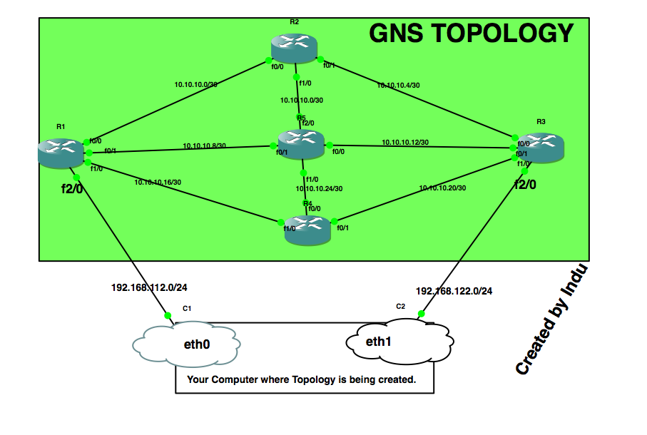
To implement the integration of virtual network in GNS with the external physical network, I created a virtual topology using Cisco routers as shown in the diagram below:
In my experiment above, i've selected 10.10.10.0/24 network and subneted into small networks each accommodating only two usable IP addresses. The topology shown above is configured and network within the GNS is working fine i.e ping among each node work correctly.
Now, let's jump into the main point of this blog post. Can we connect this virtual network in GNS with the real external network? Can we pass the real traffic from our servers/computers located in different subnet through this GNS topology?
The answer is yes, we can. And yes, ideally to the second problem, the computer should have two NIC cards. One is connected to X network & the other is connected to the Y network.
Let's say you've a few servers which are located in 192.168.112.0/24 subnet and others are located in 192.168.122.0/24 subnet. Now, you want to communicate between the servers located in different subnets via GNS topology created above.
Let's suppose the two interfaces of the computer where GNS topology is being created, are eth0 and eth1.
Step1: Add two clouds in GNS topology and attach eth0 interface to cloud1, eth1 interface to cloud2 and connect each cloud to interface f2/0 of the GNS routers R1 and R2 respectively as shown in the diagram above.
Step2: Configure the IP address say 192.168.112.100/24 subnet on interface f2/0 of router R1(which is connected to the first cloud) & configure the IP address 192.168.122.100/24 on interface f2/0 of router R2(which is connected to the second cloud).
Step3: Now on your external server S1(which belongs to 192.168.112.0/24 subnet), add a route for 192.168.122.0/24 with gateway address as 192.168.112.100( IP address of GNS router R1:f2/0) so that traffic from server S1 enters into virtual GNS topology.
Step4: Now on your external server S2(which belongs to 192.168.122.0/24 subnet), add a route for 192.168.112.0/24 with gateway address as 192.168.122.100( IP address of GNS router R2:f2/0) so that traffic from server S2 enters into virtual GNS topology.
That's all you need to do. To verify that your traffic from server S1 to S2 is passing via virtual GNS topology, you can do traceroute to server S2 from S1:
traceroute 192.168.122.140 (server S2 IP address)
1 192.168.112.100 (192.168.112.100) 10.137 ms 0.723 ms 0.702 ms
2 10.10.10.2 (10.10.10.2) 11.17 ms 0.73 ms 0.60 ms
3 10.10.10.6 (10.10.10.6) 10.37 ms 0.71 ms 0.712 ms

Comments